

“As an progressive leader in connectivity, TE Connectivity is proud to introduce the 0.Four millimeter wonderful pitch board-to-FPC connector solution with built-in EMI shield. “We imagine the distinctive design with integrated shielding capability is one thing our customers are going to love. It lowers the general profile peak of their devices, and streamlines their inside reliability testing course of. …a spring clip, which supplies robust shield retention. Our new EMI-shielded board-to-flex connector is a part of our full line-up of advantageous pitch board-to-board connector options. Our commitment is producing high efficiency, excessive reliability, board-to-board and board-to-FPC connectors that allow our customers to supply some of probably the most advance and slimmest shopper gadgets. Our current 0.4 millimeter pitch board-to-board connector has a sturdy body structure to eradicate housing breakage… …and is manufactured in a highly automated manufacturing setting to ensure constant quality. Our new 0.35 millimeter pitch board-to-board connector with a locking peg design… …gives a stronger retention pressure than business options. The tighter pitch also enables even smaller board footprints. Everyday connectors are rolling off our manufacturing line offering prime quality, high expertise merchandise.
The PCB pins can legitimately be known as the inspiration of each PCB design. Just like the way in which PCBs do, pins operate like the interconnect system as well as various plug-in applications. The circuit board design does indeed have a big amount of functionality because of hooks. Circuit board pins could be pushed in to circuit, swaged, and, for many circumstances, soldered it to Circuit board with a view to attach them to it. A needed conductive channel for the electrical circuit is offered by PCB pins. Because the mechanical interface, it offers an meeting module energy. What are the Common PCB connector types? How Can PCB Connector Be Tested? In order to attach two parts and maybe a circuit board electrically, PCB header pins is steadily employed. Although there are quite a few completely different kinds of PCB header pins, they’re sometimes male connectors arranged inside a row and spaced apart by a set distance and range.
 Such parts that are difficult to mount on typical connectors or SMT PCB connector circuit boards are steadily mounted using the PCB pin socket. The PCB pin socket is usually used on the Circuit board to select such options having single contact points. If you have any questions concerning where and just how to use SMT PCB connector (http://vitiligosocietymanipur.com), you could call us at our internet site. The ranges as well as dimensions of PCB pin sockets make it easier for shoppers to select a number of of their options based mostly on their needs. During recent years, press-fit pins have developed, making it less complicated for engineers and designers to use the press-fit and solderless connectors. The PCB pins remain easy to make the most of and produce the means of production much less costly in addition to being more accessible in contrast to the conventional methods. The engineer will find it much easier to debug a circuit in this case. The parts installed on the Circuit board are mechanically supported by PCB alignment as well as PCB guide pins. Alternatively, PCB solder pins is among the many most frequently utilized PCB pins when such connectors are hooked up to the circuit board top.
 Their typical uses are within the creation of circuit boards and prototypes. Jumper pins on PCBs are regularly utilized to provide a path of conduction over a bypass element of an electrical circuit that is open or closed. They’re obligatory because the bypass connection have to be made for the electronic parts utilized in PCB board by the designer. The PCB terminal pins were made to satisfy the increasing wants of the electronics sector. The PCB’s terminal pins offer separate, excessive-current connections. The designer can create multiple set up schemes to serve the designs because of the numerous sorts and patterns of the PCB pins. Engineers now find it much less complicated to function on prototypes or completed PCB designs due to PCB pin advances and enhancements. Many extra intricate patterns that would have seemed inconceivable to perform using standard strategies have now been made viable thanks to these breakthroughs. How Does a PCB Connector Work?
The PCB connector is often situated on the circuit board and are often utilized in transferring energy or indicators from one Circuit board to a different, in addition to from some other source contained in the unit, from or to the PCB. Because the Circuit boards should not permanently linked to each other and could possibly be put collectively later during a technique of manufacturing, connectors provide a easy method to design. What are the Common PCB connector sorts? PCB board connections are utilized in a large variety of gadgets. The design therefore must be acceptable for the sort, size, in addition to function. This makes a variety of PCB connector assembly connector choices accessible. A cable is connected to a circuit board utilizing this type of PCB connection. The tool facilitates connections inside circuits. These are primarily a sequence of pins having varied spacings, also referred to as the pin headers. There may be 0.197, 0.2, or 0.1 inches between every gap. Manufacturers can hyperlink PCBs with out the need for a cable because of the board-to-board connectors.
 The PCB pins can legitimately be known as the foundation of each PCB design. Similar to the best way PCBs do, pins operate like the interconnect system in addition to various plug-in applications. The circuit board design does certainly have a major amount of performance because of hooks. Circuit board pins might be pushed in to circuit, swaged, and, for most circumstances, soldered it to Circuit board with a purpose to attach them to it. A needed conductive channel for the electrical circuit is offered by PCB pins. As the mechanical interface, it offers an assembly module power. What are the Common PCB connector types? How Can PCB Connector Be Tested? In order to connect two components and maybe a circuit board electrically, PCB header pins is often employed. Although there are quite a few completely different sorts of PCB header pins, they’re sometimes male connectors organized inside a row and spaced apart by a set distance and vary.
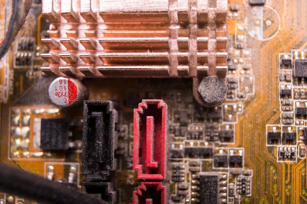
 Backplane connectors: The sort of connector deserves its own category, each attributable to its must accommodate high data rates and very rugged development. Standardized connectors: Some connectors could also be developed to satisfy very particular business standards past edge connector kinds for add-in playing cards. Standards organizations which have defined specific connector styles embrace VITA (for backplanes), PCI-SIG (PCIe playing cards), IEEE (e.g., 1386 normal for mezzanine), JTAG, Pc/104 (square-submit pin headers), and others. There are lots of other connectors that don’t fall into one of many above classes. The picture under shows an instance of some typical merchandise that fall inside these categories. The picture above is only a subset of all of the totally different board-to-board connectors available on the market. Obviously, there are lots of variations on these connectors with different pin/pad counts, key/shroud kinds, mounting types (SMD vs. When you’re wanting by a vendor’s webpage or filtering via a components search engine, there are a few different ways distributors will categorize their elements.